Dzisiaj będzie krótko. Skończyłem program dla ESP oraz rozrysowałem schemat.
Oto prototyp w akcji:
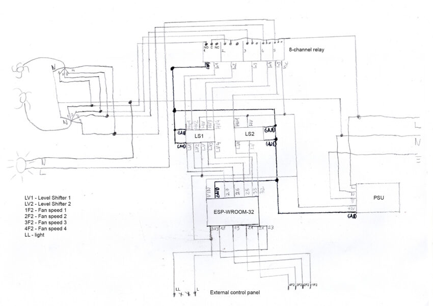
Jak widać, przekaźnik numer 5 działa niezależnie od przekaźników 1-4. To celowe, ponieważ przekaźniki 1-4 będą sterowały pracą wentylatora, a przekaźnik 5 – oświetleniem. Działa również sterowanie zewnętrzne przeznaczne do panelu okapu. Tutaj kod programu:
esphome:
  name: okap
  friendly_name: okap

esp32:
  board: esp32dev
  framework:
    type: arduino

# Enable logging
logger:

# Enable Home Assistant API
api:
  encryption:
    key: ####################

ota:
  password: ####################

wifi:
  ssid: ####################
  password: ####################

captive_portal:

web_server:

switch:
  - platform: gpio
    pin:
      number: GPIO27
      inverted: True
    name: "Relay 1"
    id: relay1
    interlock: [relay2,relay3,relay4]
  - platform: gpio
    pin:
      number: GPIO26
      inverted: True
    name: "Relay 2"
    id: relay2
    interlock: [relay1,relay3,relay4]
  - platform: gpio
    pin:
      number: GPIO25
      inverted: True
    name: "Relay 3"
    id: relay3
    interlock: [relay1,relay2,relay4]
  - platform: gpio
    pin:
      number: GPIO33
      inverted: True
    name: "Relay 4"
    id: relay4
    interlock: [relay1,relay2,relay3]
  - platform: gpio
    pin:
      number: GPIO32
      inverted: True
    name: "Relay 5"
    id: relay5

binary_sensor:
  - platform: gpio
    pin:
      number: GPIO18
      mode:
        input: true
        pulldown: true
    name: "FAN1 input / GPIO18"
    device_class: running
    on_press:
      switch.turn_on: relay1
    on_release:
      switch.turn_off: relay1
  - platform: gpio
    pin:
      number: GPIO19
      mode:
        input: true
        pulldown: true
    name: "FAN2 input / GPIO19"
    device_class: running
    on_press:
      switch.turn_on: relay2
    on_release:
      switch.turn_off: relay2
  - platform: gpio
    pin:
      number: GPIO21
      mode:
        input: true
        pulldown: true
    name: "FAN3 input / GPIO21"
    device_class: running
    on_press:
      switch.turn_on: relay3
    on_release:
      switch.turn_off: relay3
  - platform: gpio
    pin:
      number: GPIO22
      mode:
        input: true
        pulldown: true
    name: "FAN4 input / GPIO22"
    device_class: running
    on_press:
      switch.turn_on: relay4
    on_release:
      switch.turn_off: relay4
  - platform: gpio
    pin:
      number: GPIO23
      mode:
        input: true
        pulldown: true
    name: "Light input / GPIO23"
    device_class: light
    on_press:
      switch.turn_on: relay5
    on_release:
      switch.turn_off: relay5
Trochę przepastny kod wyszedł, a to w zasadzie tylko kopiuj-wklej…
Poniżej natomiast, schemat całego układu.

„External control panel” to po prostu panel okapu, a konkretniej odrysowane piny tegoż panelu jak ze zdjęcia:
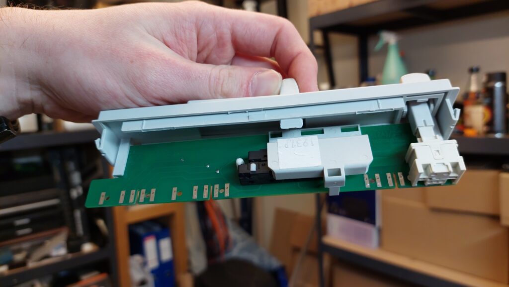
Trochę obawiam się projektowania płytki, bo będzie dość skomplikowana… Zobaczymy jak to w praniu wyjdzie 🙂